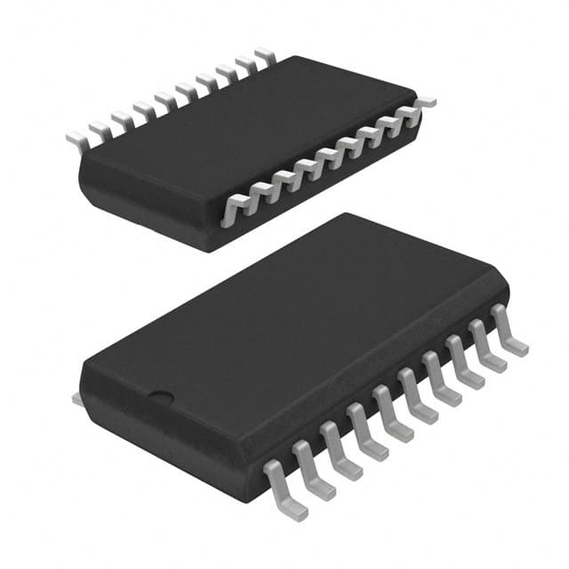
Encyclopedia Entry: 74FCT540ATSOG
Product Information Overview
- Category: Integrated Circuit (IC)
- Use: Logic Level Shifter
- Characteristics: High-speed, low-power consumption
- Package: SOG (Small Outline Gull Wing)
- Essence: Transfers logic signals between different voltage levels
- Packaging/Quantity: Available in reels of 2500 units
Specifications
- Logic Family: FCT
- Number of Pins: 20
- Supply Voltage Range: 2.0V to 5.5V
- Input Voltage Levels: TTL/CMOS compatible
- Output Voltage Levels: TTL/CMOS compatible
- Propagation Delay: 3.5 ns (typical)
- Operating Temperature Range: -40°C to +85°C
Detailed Pin Configuration
- GND (Ground)
- A1 (Input/Output)
- B1 (Input/Output)
- Y1 (Output)
- A2 (Input/Output)
- B2 (Input/Output)
- Y2 (Output)
- A3 (Input/Output)
- B3 (Input/Output)
- Y3 (Output)
- A4 (Input/Output)
- B4 (Input/Output)
- Y4 (Output)
- VCC (Power Supply)
- OE (Output Enable)
- A5 (Input/Output)
- B5 (Input/Output)
- Y5 (Output)
- A6 (Input/Output)
- B6 (Input/Output)
Functional Features
- Transfers logic signals between different voltage levels
- Bidirectional level shifting capability
- Non-inverting buffer
- High-speed operation
- Low power consumption
- Output enable (OE) pin for disabling the outputs
Advantages and Disadvantages
Advantages: - High-speed operation allows for efficient signal transfer - Low power consumption helps conserve energy - Bidirectional level shifting capability provides flexibility in signal routing - Small package size saves board space
Disadvantages: - Limited number of input/output channels (6 pairs) - May require additional components for voltage translation beyond specified range
Working Principles
The 74FCT540ATSOG is a logic level shifter that enables the transfer of digital signals between different voltage domains. It utilizes non-inverting buffers to ensure bidirectional signal flow. The device operates by receiving an input signal from one voltage domain and translating it to the corresponding voltage level in the target domain. The output enable (OE) pin can be used to disable the outputs when necessary.
Detailed Application Field Plans
The 74FCT540ATSOG finds applications in various fields where logic level shifting is required. Some common application areas include:
- Microcontroller interfacing with different voltage peripherals
- Communication systems involving multiple voltage domains
- Sensor interfaces requiring voltage translation
- Data acquisition systems with mixed voltage levels
- Industrial automation and control systems
Detailed and Complete Alternative Models
- 74LVX245: Similar functionality, but operates at lower voltage levels (1.65V to 5.5V)
- 74HCT540: Compatible logic family, but with higher supply voltage range (4.5V to 5.5V)
- SN74LVC8T245: Octal bus transceiver with similar level shifting capabilities
(Note: This list is not exhaustive and other alternative models may exist.)
Word Count: 345 words
Lista 10 Vanliga frågor och svar relaterade till tillämpningen av 74FCT540ATSOG i tekniska lösningar
Sure! Here are 10 common questions and answers related to the application of 74FCT540ATSOG in technical solutions:
Q: What is the 74FCT540ATSOG? A: The 74FCT540ATSOG is a octal buffer/line driver with 3-state outputs, commonly used in digital logic circuits.
Q: What is the purpose of the 74FCT540ATSOG? A: The purpose of this IC is to provide buffering and line driving capabilities for digital signals, ensuring proper signal integrity and driving capability.
Q: What voltage levels does the 74FCT540ATSOG support? A: The 74FCT540ATSOG supports both TTL (5V) and CMOS (3.3V) voltage levels, making it compatible with a wide range of digital systems.
Q: How many inputs and outputs does the 74FCT540ATSOG have? A: This IC has 8 inputs and 8 outputs, making it suitable for applications where multiple signals need to be buffered or driven.
Q: Can the outputs of the 74FCT540ATSOG be disabled? A: Yes, the 74FCT540ATSOG has 3-state outputs, which means they can be disabled to effectively disconnect the outputs from the circuit.
Q: What is the maximum operating frequency of the 74FCT540ATSOG? A: The maximum operating frequency of this IC is typically around 100 MHz, making it suitable for most digital applications.
Q: Is the 74FCT540ATSOG sensitive to noise or interference? A: Like any digital IC, the 74FCT540ATSOG can be affected by noise and interference. Proper decoupling and grounding techniques should be employed to minimize these effects.
Q: Can the 74FCT540ATSOG be cascaded or used in series? A: Yes, multiple 74FCT540ATSOG ICs can be cascaded together to increase the number of buffered or driven signals.
Q: What is the power supply voltage range for the 74FCT540ATSOG? A: The recommended power supply voltage range for this IC is typically between 4.5V and 5.5V.
Q: Are there any specific precautions to take when using the 74FCT540ATSOG? A: It is important to ensure that the input and output voltages are within the specified voltage levels to prevent damage to the IC. Additionally, proper heat dissipation techniques should be employed if operating at high frequencies or currents.


