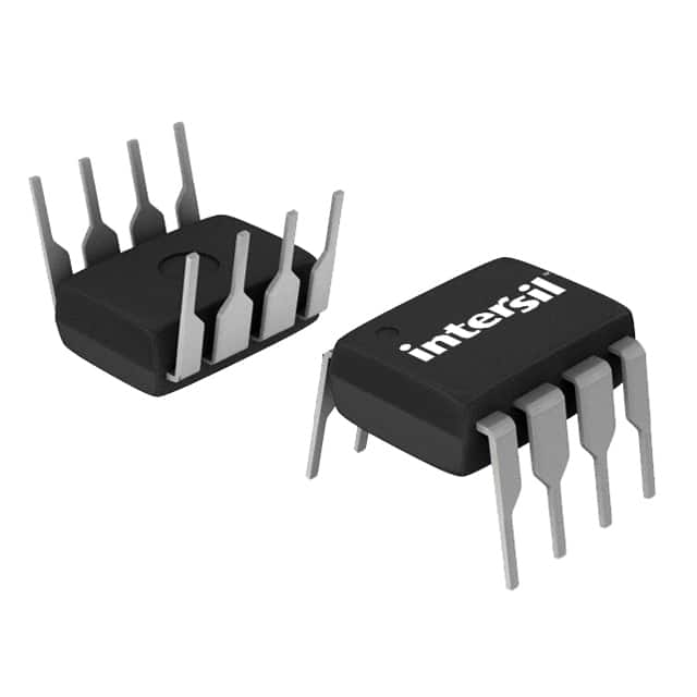
X9C104PI
Product Overview
- Category: Integrated Circuit (IC)
- Use: Digital Potentiometer
- Characteristics: Non-volatile, 100-tap, Increment/Decrement Interface
- Package: PDIP (Plastic Dual In-line Package)
- Essence: Adjustable resistor with digital control
- Packaging/Quantity: Tube packaging, 25 pieces per tube
Specifications
- Resistance Range: 10 kΩ
- Number of Taps: 100
- Supply Voltage: 2.7V to 5.5V
- Interface: Increment/Decrement
- Non-volatile Memory: Yes
- Temperature Range: -40°C to +85°C
- Package Type: PDIP-8
Detailed Pin Configuration
The X9C104PI has a total of 8 pins arranged as follows:
- VCC: Supply voltage input
- H: High terminal of the resistor element
- U/D: Increment/Decrement control input
- CS: Chip select input
- INC: Increment control input
- DEC: Decrement control input
- W: Wiper terminal of the resistor element
- GND: Ground reference
Functional Features
- Non-volatile memory allows the device to retain its settings even when power is removed.
- Increment/Decrement interface enables easy digital control of resistance.
- 100-tap resolution provides fine-grained adjustment capabilities.
- Wide supply voltage range allows for flexibility in various applications.
Advantages and Disadvantages
Advantages: - Non-volatile memory ensures that the device retains its settings, eliminating the need for recalibration. - Increment/Decrement interface simplifies the control process. - Fine-grained adjustment capability allows for precise tuning.
Disadvantages: - Limited resistance range of 10 kΩ may not be suitable for all applications. - PDIP package may not be as compact as other surface-mount packages.
Working Principles
The X9C104PI is based on the concept of a digital potentiometer. It consists of a resistor network and a wiper terminal that can be moved digitally to adjust the resistance value. The device utilizes non-volatile memory to store the wiper position, ensuring that the resistance setting is retained even when power is removed.
Detailed Application Field Plans
The X9C104PI finds applications in various fields, including:
- Audio Equipment: Volume control, tone adjustment
- Industrial Automation: Calibration, process control
- Test and Measurement: Signal conditioning, calibration
- Consumer Electronics: Brightness control, contrast adjustment
Detailed and Complete Alternative Models
- X9C103PI: 10 kΩ, 50-tap digital potentiometer
- X9C102PI: 10 kΩ, 25-tap digital potentiometer
- X9C101PI: 10 kΩ, 10-tap digital potentiometer
- X9C503PI: 50 kΩ, 100-tap digital potentiometer
- X9C502PI: 50 kΩ, 50-tap digital potentiometer
These alternative models provide different resistance ranges and tap resolutions to suit specific application requirements.
Word count: 314 words
Lista 10 Vanliga frågor och svar relaterade till tillämpningen av X9C104PI i tekniska lösningar
Sure! Here are 10 common questions and answers related to the application of X9C104PI in technical solutions:
Q: What is X9C104PI? A: X9C104PI is a digitally controlled potentiometer, also known as a digital potentiometer, which can be used to vary resistance electronically.
Q: How does X9C104PI work? A: X9C104PI consists of a series of resistive elements connected between two terminals. The wiper position on these elements can be adjusted digitally using control signals.
Q: What is the purpose of using X9C104PI in technical solutions? A: X9C104PI is commonly used in applications where precise resistance adjustments are required, such as audio volume control, light dimming, or motor speed control.
Q: What is the maximum resistance range of X9C104PI? A: X9C104PI has a maximum resistance range of 100 kilohms (kΩ).
Q: Can X9C104PI be used in both analog and digital circuits? A: Yes, X9C104PI can be used in both analog and digital circuits, depending on the specific application requirements.
Q: How is X9C104PI controlled? A: X9C104PI is controlled through a serial interface, typically using a microcontroller or other digital devices.
Q: What is the power supply voltage range for X9C104PI? A: X9C104PI operates within a power supply voltage range of 2.7V to 5.5V.
Q: Can X9C104PI handle high currents? A: No, X9C104PI is designed for low current applications. It is not suitable for handling high currents.
Q: Is X9C104PI a non-volatile memory device? A: Yes, X9C104PI has non-volatile memory, which means it retains its wiper position even when power is removed.
Q: Are there any limitations to using X9C104PI? A: One limitation of X9C104PI is that it has a limited number of write cycles (typically around 100,000), so care should be taken to avoid excessive writes that could lead to premature failure.
Please note that the answers provided here are general and may vary depending on the specific datasheet and application requirements.


