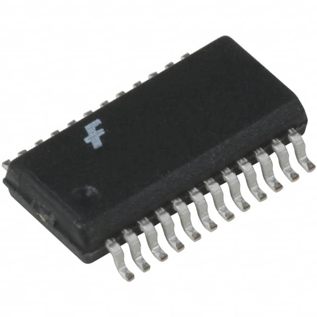
Encyclopedia Entry: 74ACTQ543QSC
Product Overview
Category
The 74ACTQ543QSC belongs to the category of integrated circuits (ICs).
Use
This IC is commonly used in digital electronic systems for data storage and manipulation.
Characteristics
- High-speed operation
- Low power consumption
- Wide operating voltage range
- Compatibility with various logic families
Package
The 74ACTQ543QSC is available in a small outline integrated circuit (SOIC) package.
Essence
This IC serves as an octal transparent latch with three-state outputs, designed to store and control data in digital systems.
Packaging/Quantity
The 74ACTQ543QSC is typically packaged in reels or tubes, with quantities varying depending on the manufacturer.
Specifications
- Supply Voltage Range: 2.0V to 6.0V
- Input Voltage Range: 0V to VCC
- Output Voltage Range: 0V to VCC
- Operating Temperature Range: -40°C to +85°C
- Maximum Clock Frequency: 200MHz
Detailed Pin Configuration
The 74ACTQ543QSC has a total of 20 pins, which are assigned specific functions as follows:
- Pin 1: Output Enable (OE)
- Pin 2: Data Input D0
- Pin 3: Data Input D1
- Pin 4: Data Input D2
- Pin 5: Data Input D3
- Pin 6: Data Input D4
- Pin 7: Data Input D5
- Pin 8: Data Input D6
- Pin 9: Data Input D7
- Pin 10: GND (Ground)
- Pin 11: Clock Input (CLK)
- Pin 12: Latch Enable (LE)
- Pin 13: Output Q0
- Pin 14: Output Q1
- Pin 15: Output Q2
- Pin 16: Output Q3
- Pin 17: Output Q4
- Pin 18: Output Q5
- Pin 19: Output Q6
- Pin 20: Output Q7
Functional Features
- Octal transparent latch with three-state outputs
- Data inputs are latched to the outputs when the latch enable (LE) signal is high
- Outputs can be disabled by setting the output enable (OE) signal low
- High-speed operation allows for efficient data storage and retrieval
Advantages and Disadvantages
Advantages
- High-speed operation enables quick data processing
- Low power consumption helps conserve energy
- Wide operating voltage range provides flexibility in various applications
- Compatibility with different logic families enhances versatility
Disadvantages
- Limited number of output pins may restrict certain complex applications
- Sensitivity to electrostatic discharge (ESD) requires proper handling precautions
Working Principles
The 74ACTQ543QSC operates based on the principle of transparent latching. When the latch enable (LE) signal is high, the data inputs (D0-D7) are transferred to the outputs (Q0-Q7). The outputs can be enabled or disabled using the output enable (OE) signal. This IC utilizes advanced semiconductor technology to achieve high-speed operation and low power consumption.
Detailed Application Field Plans
The 74ACTQ543QSC finds extensive use in various digital systems, including but not limited to: - Microprocessors - Memory modules - Communication devices - Industrial control systems - Automotive electronics
Detailed and Complete Alternative Models
Some alternative models that serve similar functions to the 74ACTQ543QSC include: - 74HC543: High-speed CMOS octal latch with three-state outputs - 74LS543: Low-power Schottky TTL octal transparent latch - CD74ACT573: Octal transparent latch with tri-state outputs
These alternative models offer different specifications and characteristics, allowing users to choose the most suitable option for their specific requirements.
In conclusion, the 74ACTQ543QSC is a high-speed octal transparent latch IC that provides efficient data storage and manipulation capabilities in digital electronic systems. Its compatibility with various logic families, low power consumption, and wide operating voltage range make it a versatile choice for numerous applications. However, its limited number of output pins and sensitivity to ESD should be considered when implementing this IC.
Lista 10 Vanliga frågor och svar relaterade till tillämpningen av 74ACTQ543QSC i tekniska lösningar
Sure! Here are 10 common questions and answers related to the application of 74ACTQ543QSC in technical solutions:
Question: What is the 74ACTQ543QSC?
Answer: The 74ACTQ543QSC is a octal registered transceiver with tri-state outputs, commonly used in digital systems.Question: What is the purpose of the 74ACTQ543QSC?
Answer: The purpose of this component is to enable bidirectional data transfer between two buses or systems.Question: How many bits can the 74ACTQ543QSC handle?
Answer: This component can handle 8 bits of data, as it is an octal transceiver.Question: What is the voltage range supported by the 74ACTQ543QSC?
Answer: The 74ACTQ543QSC supports a voltage range of 2V to 6V, making it compatible with a wide range of digital systems.Question: Can the 74ACTQ543QSC be used in both synchronous and asynchronous applications?
Answer: Yes, the 74ACTQ543QSC can be used in both synchronous and asynchronous applications, depending on the requirements of the system.Question: Does the 74ACTQ543QSC have built-in protection against bus contention?
Answer: Yes, the 74ACTQ543QSC has built-in bus hold circuitry that prevents bus contention when the outputs are in the high-impedance state.Question: What is the maximum operating frequency of the 74ACTQ543QSC?
Answer: The maximum operating frequency of this component is typically around 200MHz, but it may vary depending on the specific implementation.Question: Can the 74ACTQ543QSC be used in both 3.3V and 5V systems?
Answer: Yes, the 74ACTQ543QSC is compatible with both 3.3V and 5V systems, making it versatile for various applications.Question: Does the 74ACTQ543QSC have any power-saving features?
Answer: No, the 74ACTQ543QSC does not have any specific power-saving features. However, it has a low-power consumption design compared to some other transceivers.Question: Are there any recommended layout guidelines for using the 74ACTQ543QSC?
Answer: Yes, it is recommended to follow the layout guidelines provided in the datasheet to ensure proper signal integrity and minimize noise interference.
Please note that these answers are general and may vary depending on the specific implementation and requirements of your technical solution.


