

74F544SPC
Product Overview
Category
The 74F544SPC belongs to the category of integrated circuits (ICs) and specifically falls under the family of flip-flops.
Use
This product is primarily used in digital electronics for storing a single bit of data. It can be employed in various applications such as memory units, registers, and counters.
Characteristics
- The 74F544SPC is a D-type flip-flop with an edge-triggered clock input.
- It operates on a wide voltage range, typically between 4.5V and 5.5V.
- This IC offers high-speed operation, making it suitable for time-critical applications.
- It has a compact size and low power consumption, making it ideal for portable electronic devices.
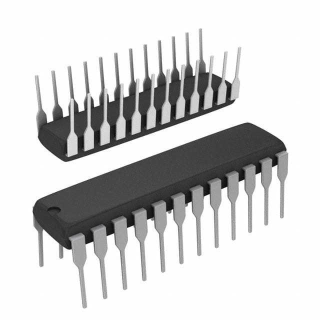
Package
The 74F544SPC is available in a small outline package (SOIC) format. This package provides ease of handling and compatibility with modern PCB manufacturing techniques.
Essence
The essence of the 74F544SPC lies in its ability to store and manipulate digital information reliably and efficiently.
Packaging/Quantity
The 74F544SPC is commonly packaged in reels or tubes, containing a specific quantity of ICs per package. The exact quantity may vary depending on the manufacturer and customer requirements.
Specifications
- Supply Voltage: 4.5V - 5.5V
- Operating Temperature Range: -40°C to +85°C
- Input High Voltage: 2V (min)
- Input Low Voltage: 0.8V (max)
- Output High Voltage: 2.7V (min)
- Output Low Voltage: 0.5V (max)
- Propagation Delay Time: 6 ns (typical)
Detailed Pin Configuration
The 74F544SPC consists of 20 pins, each serving a specific function. The pin configuration is as follows:
- D0: Data Input 0
- D1: Data Input 1
- D2: Data Input 2
- D3: Data Input 3
- D4: Data Input 4
- D5: Data Input 5
- D6: Data Input 6
- D7: Data Input 7
- GND: Ground
- Q0: Output 0
- Q1: Output 1
- Q2: Output 2
- Q3: Output 3
- Q4: Output 4
- Q5: Output 5
- Q6: Output 6
- Q7: Output 7
- CLK: Clock Input
- OE: Output Enable
- VCC: Power Supply
Functional Features
The 74F544SPC offers the following functional features:
- Edge-triggered clock input for synchronized data storage.
- Eight data inputs (D0-D7) for storing digital information.
- Eight corresponding output pins (Q0-Q7) to retrieve stored data.
- Output enable (OE) pin to control the output state.
- High-speed operation for time-critical applications.
Advantages and Disadvantages
Advantages
- Wide operating voltage range allows compatibility with various systems.
- Compact size and low power consumption make it suitable for portable devices.
- High-speed operation enables efficient data processing.
- Reliable and durable construction ensures long-term performance.
Disadvantages
- Limited storage capacity compared to other memory devices.
- Requires external components for complete functionality.
- Sensitive to electrostatic discharge (ESD), necessitating proper handling precautions.
Working Principles
The 74F544SPC operates based on the principles of flip-flops. It utilizes a clock signal to latch and store the input data at the rising or falling edge of the clock pulse. The stored data remains unchanged until the next clock cycle, allowing for stable data storage and retrieval.
Detailed Application Field Plans
The 74F544SPC finds applications in various fields, including:
- Computer memory units
- Register circuits
- Digital counters
- Data communication systems
- Control systems
- Microcontrollers
Its versatility and reliability make it suitable for a wide range of digital electronic applications.
Detailed and Complete Alternative Models
There are several alternative models available that offer similar functionality to the 74F544SPC. Some notable alternatives include:
- 74HC574: This IC provides octal D-type flip-flops with similar characteristics and pin configuration.
- CD4013: A dual D-type flip-flop IC offering comparable features and performance.
- SN74LS74: Another popular choice for D-type flip-flops, widely used in digital systems.
These alternative models can be considered based on specific project requirements and availability
Lista 10 Vanliga frågor och svar relaterade till tillämpningen av 74F544SPC i tekniska lösningar
Sure! Here are 10 common questions and answers related to the application of 74F544SPC in technical solutions:
Q: What is the 74F544SPC? A: The 74F544SPC is a type of integrated circuit (IC) commonly used as an octal transparent latch with 3-state outputs.
Q: What are the typical applications of the 74F544SPC? A: The 74F544SPC is often used in digital systems for data storage, bus interfacing, and signal buffering.
Q: How many latch circuits are there in the 74F544SPC? A: The 74F544SPC contains eight individual latch circuits, making it an octal latch.
Q: What is the purpose of the 3-state outputs in the 74F544SPC? A: The 3-state outputs allow multiple devices to share a common bus without interfering with each other's signals.
Q: What is the maximum operating frequency of the 74F544SPC? A: The maximum operating frequency of the 74F544SPC is typically around 100 MHz.
Q: Can the 74F544SPC be used with both TTL and CMOS logic levels? A: Yes, the 74F544SPC is compatible with both TTL and CMOS logic levels, making it versatile for various applications.
Q: What is the power supply voltage range for the 74F544SPC? A: The 74F544SPC typically operates within a power supply voltage range of 4.5V to 5.5V.
Q: Does the 74F544SPC have any built-in protection features? A: Yes, the 74F544SPC has built-in diode clamps to protect against electrostatic discharge (ESD) and other voltage spikes.
Q: Can the 74F544SPC be used in high-speed data transfer applications? A: Yes, the 74F544SPC is capable of handling high-speed data transfers due to its fast propagation delay and setup/hold times.
Q: Are there any specific layout considerations when using the 74F544SPC? A: It is recommended to follow proper PCB layout guidelines, such as minimizing trace lengths and providing adequate decoupling capacitors, to ensure optimal performance of the 74F544SPC.
Please note that these answers are general and may vary depending on the specific datasheet and manufacturer's recommendations for the 74F544SPC.