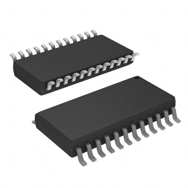
74F657SC
Product Overview
- Category: Integrated Circuit (IC)
- Use: Data Bus Transceiver
- Characteristics: High-speed, bidirectional data transfer, compatible with TTL logic levels
- Package: 20-pin Small Outline Integrated Circuit (SOIC)
- Essence: The 74F657SC is a versatile IC that enables bidirectional data transfer between two separate data buses.
- Packaging/Quantity: Available in reels of 250 units or tubes of 25 units.
Specifications
- Supply Voltage: 4.5V to 5.5V
- Operating Temperature Range: -40°C to +85°C
- Input/Output Compatibility: TTL Logic Levels
- Data Transfer Rate: Up to 100MHz
- Propagation Delay: 6ns (max)
- Output Drive Capability: ±24mA
Detailed Pin Configuration
The 74F657SC has a total of 20 pins, each serving a specific function:
- A1: Data Bus A, Bit 1
- B1: Data Bus B, Bit 1
- A2: Data Bus A, Bit 2
- B2: Data Bus B, Bit 2
- A3: Data Bus A, Bit 3
- B3: Data Bus B, Bit 3
- A4: Data Bus A, Bit 4
- B4: Data Bus B, Bit 4
- GND: Ground
- OE: Output Enable
- DIR: Direction Control
- VCC: Supply Voltage
- B5: Data Bus B, Bit 5
- A5: Data Bus A, Bit 5
- B6: Data Bus B, Bit 6
- A6: Data Bus A, Bit 6
- B7: Data Bus B, Bit 7
- A7: Data Bus A, Bit 7
- B8: Data Bus B, Bit 8
- A8: Data Bus A, Bit 8
Functional Features
- Bidirectional data transfer between two separate data buses (A and B)
- High-speed operation, suitable for applications requiring fast data transfer
- Output enable and direction control pins provide flexibility in controlling data flow
- TTL-compatible logic levels ensure compatibility with a wide range of devices
Advantages and Disadvantages
Advantages: - High-speed data transfer capability - Versatile bidirectional functionality - Compatibility with TTL logic levels - Flexible control options
Disadvantages: - Limited to 8-bit data bus width - Requires external control signals for proper operation
Working Principles
The 74F657SC is designed to facilitate bidirectional data transfer between two separate data buses. The direction of data flow is controlled by the DIR pin. When DIR is set to logic high, data flows from bus A to bus B, and when DIR is set to logic low, data flows from bus B to bus A.
The OE (Output Enable) pin allows the user to enable or disable the output buffers. When OE is set to logic high, the outputs are enabled, allowing data to be transferred. Conversely, when OE is set to logic low, the outputs are disabled, effectively isolating the two data buses.
Detailed Application Field Plans
The 74F657SC can be used in various applications that require bidirectional data transfer between two separate data buses. Some potential application fields include:
- Microprocessor-based systems
- Data communication equipment
- Industrial automation
- Test and measurement instruments
- Automotive electronics
Detailed and Complete Alternative Models
- 74F657: Similar functionality, but available in a different package (DIP-20)
- 74HC657: CMOS logic family alternative with similar characteristics
- SN74LS657: Low-power Schottky TTL alternative with comparable features
These alternative models provide similar bidirectional data transfer capabilities and can be considered as substitutes for the 74F657SC depending on specific requirements.
Word count: 511 words
Lista 10 Vanliga frågor och svar relaterade till tillämpningen av 74F657SC i tekniska lösningar
Sure! Here are 10 common questions and answers related to the application of 74F657SC in technical solutions:
Q: What is the 74F657SC? A: The 74F657SC is a quad 2-input multiplexer with 3-state outputs, commonly used in digital logic circuits.
Q: What is the purpose of a multiplexer? A: A multiplexer is used to select one of several input signals and route it to a single output line based on control inputs.
Q: How many inputs can the 74F657SC handle? A: The 74F657SC has four independent 2-input multiplexers, allowing it to handle up to eight input signals.
Q: Can the 74F657SC handle both analog and digital signals? A: No, the 74F657SC is designed for digital signals only and does not support analog signals.
Q: What are 3-state outputs? A: 3-state outputs allow the output lines to be in three different states: high (logic 1), low (logic 0), or high impedance (disconnected).
Q: How can I control the selection of inputs in the 74F657SC? A: The 74F657SC has control inputs that determine which input signal is selected and routed to the output.
Q: What is the power supply voltage range for the 74F657SC? A: The 74F657SC typically operates with a power supply voltage range of 4.5V to 5.5V.
Q: Can the 74F657SC handle high-speed data signals? A: Yes, the 74F657SC is designed for high-speed operation and can handle data rates up to several hundred megahertz.
Q: Can I cascade multiple 74F657SC chips together? A: Yes, you can cascade multiple 74F657SC chips to increase the number of input signals that can be handled.
Q: What are some common applications for the 74F657SC? A: The 74F657SC is commonly used in digital systems for data routing, signal selection, bus switching, and multiplexing tasks.
Please note that these answers are general and may vary depending on specific implementation details and requirements.


