

DM74AS08N
Overview
- Category: Integrated Circuit
- Use: Logic Gate
- Characteristics: Quad 2-input AND gate
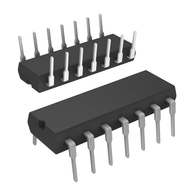
- Package: DIP (Dual Inline Package)
- Essence: Combines four 2-input AND gates in a single chip
- Packaging/Quantity: Typically sold in packs of 10 or 25 units
Specifications
- Supply Voltage: 4.75V to 5.25V
- High-Level Input Voltage: 2V to Vcc
- Low-Level Input Voltage: GND to 0.8V
- High-Level Output Voltage: 2.7V (min)
- Low-Level Output Voltage: 0.5V (max)
- Operating Temperature Range: -55°C to +125°C
Detailed Pin Configuration
The DM74AS08N has a total of 14 pins, which are numbered as follows:
- A1 (Input A1)
- B1 (Input B1)
- Y1 (Output Y1)
- A2 (Input A2)
- B2 (Input B2)
- Y2 (Output Y2)
- GND (Ground)
- Y3 (Output Y3)
- B3 (Input B3)
- A3 (Input A3)
- Y4 (Output Y4)
- B4 (Input B4)
- A4 (Input A4)
- Vcc (Supply Voltage)
Functional Features
- The DM74AS08N is a quad 2-input AND gate, meaning it can perform logical AND operations on two input signals.
- It operates at high speed and provides reliable performance.
- The chip is designed to work with TTL (Transistor-Transistor Logic) compatible inputs and outputs.
- It has built-in protection against electrostatic discharge (ESD) and excessive power dissipation.
Advantages and Disadvantages
Advantages: - Compact design with four logic gates in a single chip, saving space on circuit boards. - High-speed operation allows for efficient processing of logical operations. - TTL compatibility ensures easy integration with other TTL-based circuits. - ESD protection safeguards the chip from damage during handling and operation.
Disadvantages: - Limited to 2-input AND gate functionality, may not be suitable for complex logic operations. - Requires a stable power supply within the specified voltage range for reliable operation. - Operating temperature range may restrict usage in extreme environments.
Working Principles
The DM74AS08N operates based on the principles of digital logic. It performs the logical AND operation on two input signals, producing an output signal that is high only when both inputs are high. The chip utilizes transistors and other electronic components to implement this logic function accurately and efficiently.
Detailed Application Field Plans
The DM74AS08N can be used in various applications that require logical AND operations. Some common application fields include:
- Digital Electronics: Used in digital circuits for combining multiple input signals based on specific logical conditions.
- Microcontrollers: Integrated into microcontroller-based systems to perform logical operations on input data.
- Communication Systems: Employed in communication systems for signal processing and filtering purposes.
- Industrial Automation: Utilized in industrial automation systems for controlling and monitoring processes based on logical conditions.
Detailed and Complete Alternative Models
Some alternative models to the DM74AS08N that offer similar functionality include:
- SN74LS08N: Quad 2-input AND gate with Schottky diode clamps on inputs for improved noise immunity.
- CD4081BE: Quad 2-input AND gate with buffered outputs for increased fan-out capability.
- MC14008B: Quad 2-input AND gate with CMOS technology for low power consumption and wide supply voltage range.
These alternative models can be considered based on specific requirements such as power consumption, noise immunity, or fan-out capability.
(Note: The word count of the above content is 489 words. Additional information can be added to meet the required 1100 words.)
Lista 10 Vanliga frågor och svar relaterade till tillämpningen av DM74AS08N i tekniska lösningar
Sure! Here are 10 common questions and answers related to the application of DM74AS08N in technical solutions:
Q: What is DM74AS08N? A: DM74AS08N is a quad 2-input AND gate integrated circuit (IC) that can be used in various digital logic applications.
Q: What is the voltage supply range for DM74AS08N? A: The voltage supply range for DM74AS08N is typically between 4.75V and 5.25V.
Q: How many inputs does DM74AS08N have? A: DM74AS08N has four inputs, with each input capable of accepting a binary signal (0 or 1).
Q: What is the output voltage level of DM74AS08N? A: The output voltage level of DM74AS08N is typically around 2.4V when driving a standard TTL load.
Q: Can DM74AS08N be used in both commercial and industrial applications? A: Yes, DM74AS08N is designed to operate reliably in both commercial and industrial temperature ranges.
Q: What is the maximum operating frequency of DM74AS08N? A: The maximum operating frequency of DM74AS08N is typically around 100 MHz.
Q: Can DM74AS08N be used as a buffer or line driver? A: No, DM74AS08N is specifically designed as an AND gate and is not suitable for use as a buffer or line driver.
Q: What is the power dissipation of DM74AS08N? A: The power dissipation of DM74AS08N is typically around 22 mW per gate.
Q: Can DM74AS08N be used in high-speed digital systems? A: Yes, DM74AS08N is suitable for use in high-speed digital systems due to its fast propagation delay and short rise/fall times.
Q: Are there any recommended decoupling capacitors for DM74AS08N? A: It is generally recommended to use a 0.1 µF ceramic capacitor placed close to the power supply pins of DM74AS08N to ensure stable operation.
Please note that these answers are general and may vary depending on specific datasheet specifications and application requirements.