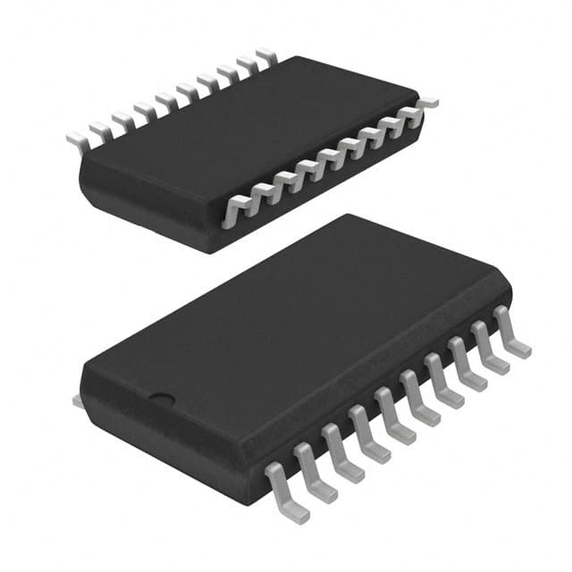
DM74AS244WM
Basic Information Overview
- Category: Integrated Circuit (IC)
- Use: Signal Buffer/Line Driver
- Characteristics:
- High-speed operation
- Wide voltage range
- Non-inverting buffer
- Package: 20-pin SOIC (Small Outline Integrated Circuit)
- Essence: Buffering and driving signals in electronic circuits
- Packaging/Quantity: Typically sold in reels of 250 or 1000 units
Specifications
- Supply Voltage Range: 4.5V to 5.5V
- Input Voltage Range: 0V to VCC
- Output Voltage Range: 0V to VCC
- Operating Temperature Range: -40°C to +85°C
- Propagation Delay Time: 9ns (typical)
- Output Current: ±24mA
- Input Capacitance: 3pF (typical)
- Output Capacitance: 6pF (typical)
Detailed Pin Configuration
The DM74AS244WM has a total of 20 pins, numbered as follows:
- GND (Ground)
- A1 (Input A1)
- B1 (Input B1)
- Y1 (Output Y1)
- A2 (Input A2)
- B2 (Input B2)
- Y2 (Output Y2)
- GND (Ground)
- Y3 (Output Y3)
- B3 (Input B3)
- A3 (Input A3)
- GND (Ground)
- Y4 (Output Y4)
- B4 (Input B4)
- A4 (Input A4)
- VCC (+5V Power Supply)
- OE (Output Enable)
- GND (Ground)
- Y5 (Output Y5)
- A5 (Input A5)
Functional Features
- Non-inverting buffer: The DM74AS244WM amplifies and reproduces input signals without changing their polarity.
- High-speed operation: It can handle signals with fast rise and fall times, making it suitable for high-frequency applications.
- Wide voltage range: The IC can operate within a broad supply voltage range, providing flexibility in various electronic systems.
Advantages and Disadvantages
Advantages: - High-speed operation enables efficient signal buffering in time-critical applications. - Wide voltage range allows compatibility with different power supply configurations. - Non-inverting buffer preserves the original signal polarity.
Disadvantages: - Limited output current may restrict its use in certain high-power applications. - Input and output capacitance may affect signal integrity in high-frequency circuits.
Working Principles
The DM74AS244WM is based on transistor-transistor logic (TTL) technology. It consists of multiple buffer gates that amplify and drive input signals to the corresponding output pins. The non-inverting nature of the buffer ensures that the output signal matches the input signal's polarity.
Detailed Application Field Plans
The DM74AS244WM finds applications in various electronic systems, including:
- Data communication: Buffering and driving signals between different components in data transmission systems.
- Microprocessor interfacing: Connecting microprocessors to peripheral devices, ensuring proper signal levels and integrity.
- Memory systems: Amplifying and driving address and data signals in memory modules.
- Industrial automation: Signal buffering and line driving in control systems and PLCs (Programmable Logic Controllers).
- Test and measurement equipment: Providing signal conditioning and amplification for accurate measurements.
Detailed and Complete Alternative Models
- SN74LS244: Similar functionality but operates at lower speeds.
- MC74HC244: Compatible with CMOS logic levels and offers higher noise immunity.
- CD74ACT244: Provides faster switching speeds and lower power consumption.
(Note: The above alternative models are just a few examples; there are several other alternatives available in the market.)
Word count: 496 words
Lista 10 Vanliga frågor och svar relaterade till tillämpningen av DM74AS244WM i tekniska lösningar
Sure! Here are 10 common questions and answers related to the application of DM74AS244WM in technical solutions:
Q: What is DM74AS244WM? A: DM74AS244WM is a specific type of integrated circuit (IC) chip commonly used as a buffer or line driver in digital electronics.
Q: What is the purpose of using DM74AS244WM in technical solutions? A: DM74AS244WM is used to amplify and buffer digital signals, ensuring proper signal integrity and driving capability in various electronic circuits.
Q: What voltage levels does DM74AS244WM support? A: DM74AS244WM typically supports TTL (Transistor-Transistor Logic) voltage levels, which are commonly used in many digital systems.
Q: How many channels or buffers are available in DM74AS244WM? A: DM74AS244WM has 8 independent channels or buffers, allowing it to handle multiple digital signals simultaneously.
Q: Can DM74AS244WM be used for bidirectional communication? A: No, DM74AS244WM is unidirectional and can only be used for one-way signal transmission.
Q: What is the maximum operating frequency of DM74AS244WM? A: The maximum operating frequency of DM74AS244WM is typically around 25 MHz, but it may vary depending on the specific datasheet.
Q: Is DM74AS244WM compatible with other logic families like CMOS? A: Yes, DM74AS244WM can be used with other logic families like CMOS, but level shifting may be required due to different voltage requirements.
Q: Can DM74AS244WM drive capacitive loads directly? A: DM74AS244WM has limited output current capability, so it is recommended to use additional buffer or driver circuits when driving capacitive loads.
Q: What is the power supply voltage range for DM74AS244WM? A: The typical power supply voltage range for DM74AS244WM is 4.5V to 5.5V, but it is always best to refer to the datasheet for accurate specifications.
Q: Are there any specific precautions to consider when using DM74AS244WM? A: It is important to avoid exceeding the maximum ratings specified in the datasheet, provide proper decoupling capacitors, and follow recommended PCB layout guidelines for optimal performance.
Please note that these answers are general and may vary depending on the specific manufacturer's datasheet for DM74AS244WM.


