

MC74HC4851ADTR2G
Product Overview
- Category: Integrated Circuit (IC)
- Use: Multiplexer/Demultiplexer
- Characteristics: High-Speed CMOS Logic, 8-Channel Analog Multiplexer/Demultiplexer
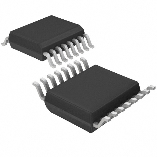
- Package: TSSOP-16
- Essence: This IC is designed to multiplex or demultiplex analog signals in various applications.
- Packaging/Quantity: Tape and Reel, 2500 units per reel
Specifications
- Supply Voltage: 2V to 6V
- Input Voltage: -0.5V to VCC + 0.5V
- Output Voltage: -0.5V to VCC + 0.5V
- Operating Temperature Range: -40°C to +85°C
- On-State Resistance: 70Ω (typical) at VCC = 4.5V
- Channel-to-Channel Crosstalk: -80dB (typical) at f = 1MHz, VCC = 4.5V
Detailed Pin Configuration
The MC74HC4851ADTR2G has a total of 16 pins arranged as follows:
___________
      |           |
   1  |    A0     | 16
   2  |    A1     | 15
   3  |    A2     | 14
   4  |    A3     | 13
   5  |    A4     | 12
   6  |    A5     | 11
   7  |    E      | 10
   8  |    Y0     | 9
      |___________|
Functional Features
- 8-channel analog multiplexer/demultiplexer
- Wide operating voltage range
- Low power consumption
- High-speed CMOS logic
- Break-before-make switching action
- Channel selection through address inputs (A0-A5)
- Enable input (E) for device control
Advantages and Disadvantages
Advantages: - Versatile multiplexing/demultiplexing capabilities - Wide operating voltage range allows compatibility with various systems - Low power consumption for energy-efficient designs - High-speed CMOS logic enables fast signal processing - Break-before-make switching action prevents signal distortion during switching
Disadvantages: - Limited to 8 channels, may not be suitable for applications requiring more channels - Requires external control signals for channel selection and device enablement
Working Principles
The MC74HC4851ADTR2G operates as an analog multiplexer/demultiplexer by selectively connecting one of the eight input channels to the output. The channel selection is determined by the address inputs (A0-A5), which are decoded internally. The enable input (E) controls the device's operation, allowing the user to enable or disable the multiplexing/demultiplexing function.
When a specific channel is selected, the corresponding analog signal is passed through the IC without significant distortion. The break-before-make switching action ensures that there is no overlap between the previous and new channel connections, preventing signal interference.
Detailed Application Field Plans
The MC74HC4851ADTR2G finds applications in various fields, including:
- Audio/Video Systems: Multiplexing audio/video signals for routing and switching purposes.
- Communication Systems: Selective routing of analog signals in telecommunication equipment.
- Test and Measurement Instruments: Switching between different test points for signal analysis.
- Industrial Control Systems: Signal routing and switching in control panels and automation systems.
- Medical Equipment: Multiplexing/demultiplexing analog signals in medical devices for diagnostics and monitoring.
Detailed and Complete Alternative Models
- CD74HC4851E: Similar 8-channel analog multiplexer/demultiplexer from Texas Instruments.
- SN74HC4851N: 8-channel CMOS analog multiplexer/demultiplexer from Texas Instruments.
- HEF4051BP: 8-channel analog multiplexer/demultiplexer from NXP Semiconductors.
These alternative models offer similar functionality and can be considered as substitutes for the MC74HC4851ADTR2G in various applications.
Word count: 534 words
Lista 10 Vanliga frågor och svar relaterade till tillämpningen av MC74HC4851ADTR2G i tekniska lösningar
Sure! Here are 10 common questions and answers related to the application of MC74HC4851ADTR2G in technical solutions:
Q1: What is MC74HC4851ADTR2G? A1: MC74HC4851ADTR2G is a multiplexer/demultiplexer integrated circuit (IC) that allows multiple analog or digital signals to be routed through a single channel.
Q2: What is the purpose of using MC74HC4851ADTR2G in technical solutions? A2: MC74HC4851ADTR2G is commonly used in technical solutions to switch between multiple input/output channels, enabling efficient signal routing and selection.
Q3: How many channels does MC74HC4851ADTR2G support? A3: MC74HC4851ADTR2G supports 8 channels, allowing for the selection of one out of eight input/output lines.
Q4: What voltage levels does MC74HC4851ADTR2G operate at? A4: MC74HC4851ADTR2G operates at a voltage range of 2V to 6V, making it compatible with various digital and analog systems.
Q5: Can MC74HC4851ADTR2G handle both analog and digital signals? A5: Yes, MC74HC4851ADTR2G can handle both analog and digital signals, making it versatile for different applications.
Q6: How does MC74HC4851ADTR2G achieve signal routing? A6: MC74HC4851ADTR2G uses control signals to select the desired input/output channel, effectively routing the signal to the desired path.
Q7: What is the maximum frequency that MC74HC4851ADTR2G can handle? A7: MC74HC4851ADTR2G can handle frequencies up to 100MHz, making it suitable for a wide range of applications.
Q8: Can MC74HC4851ADTR2G be cascaded to increase the number of channels? A8: Yes, multiple MC74HC4851ADTR2G ICs can be cascaded together to increase the number of channels and expand the signal routing capabilities.
Q9: Is MC74HC4851ADTR2G available in different package types? A9: Yes, MC74HC4851ADTR2G is available in various package types, including SOIC, TSSOP, and PDIP, providing flexibility for different PCB designs.
Q10: Are there any special considerations when using MC74HC4851ADTR2G? A10: It is important to ensure proper voltage levels, signal integrity, and appropriate decoupling capacitors when using MC74HC4851ADTR2G to achieve optimal performance.
Please note that these questions and answers are general in nature and may vary depending on specific application requirements.