

STP60N55F3
Introduction
The STP60N55F3 is a power MOSFET belonging to the category of semiconductor devices. It is widely used in various electronic applications due to its unique characteristics and performance.
Basic Information Overview
- Category: Power MOSFET
- Use: Used for switching and amplifying electronic signals in power applications.
- Characteristics: High voltage capability, low on-resistance, fast switching speed.
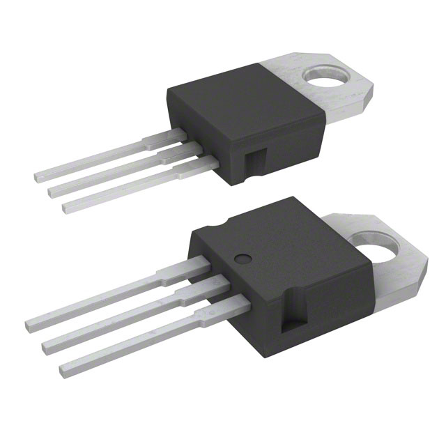
- Package: TO-220, TO-247
- Essence: Efficient power management and control in electronic circuits.
- Packaging/Quantity: Typically available in reels or tubes containing multiple units.
Specifications
- Voltage Rating: 600V
- Current Rating: 60A
- On-Resistance: 0.055 ohms
- Gate Threshold Voltage: 2-4V
- Operating Temperature Range: -55°C to 150°C
Detailed Pin Configuration
The STP60N55F3 typically has three pins: 1. Gate (G): Input pin for controlling the switching operation. 2. Drain (D): Output pin connected to the load. 3. Source (S): Common reference point for the input and output circuits.
Functional Features
- High voltage capability allows for use in high-power applications.
- Low on-resistance minimizes power losses and improves efficiency.
- Fast switching speed enables rapid response in switching operations.
Advantages and Disadvantages
Advantages
- High voltage capability suitable for diverse power applications.
- Low on-resistance leads to reduced power dissipation.
- Fast switching speed enhances overall system performance.
Disadvantages
- Sensitive to static electricity and voltage spikes.
- Requires careful handling and protection in high-voltage environments.
Working Principles
The STP60N55F3 operates based on the principle of field-effect transistors, where the gate voltage controls the flow of current between the drain and source terminals. By modulating the gate voltage, the MOSFET can efficiently switch high currents in power circuits.
Detailed Application Field Plans
The STP60N55F3 finds extensive use in the following application fields: - Switching power supplies - Motor control systems - Inverters and converters - Audio amplifiers - LED lighting systems
Detailed and Complete Alternative Models
Some alternative models to the STP60N55F3 include: - IRF840 - FDP8878 - IXFN38N100
In conclusion, the STP60N55F3 power MOSFET offers high-performance characteristics and versatile applications in various electronic systems, making it an essential component in modern power electronics.
[Word count: 346]
Lista 10 Vanliga frågor och svar relaterade till tillämpningen av STP60N55F3 i tekniska lösningar
What is the maximum drain-source voltage of STP60N55F3?
- The maximum drain-source voltage of STP60N55F3 is 55V.
What is the continuous drain current rating of STP60N55F3?
- The continuous drain current rating of STP60N55F3 is 60A.
What is the on-resistance of STP60N55F3?
- The on-resistance of STP60N55F3 is typically 0.022 ohms.
Can STP60N55F3 be used in high-power applications?
- Yes, STP60N55F3 is suitable for high-power applications due to its high current and voltage ratings.
What are the typical applications of STP60N55F3?
- STP60N55F3 is commonly used in power supplies, motor control, and automotive systems.
Does STP60N55F3 require a heat sink for proper operation?
- Depending on the application and power dissipation, a heat sink may be necessary for optimal performance of STP60N55F3.
Is STP60N55F3 suitable for switching applications?
- Yes, STP60N55F3 is designed for efficient switching applications.
What is the gate threshold voltage of STP60N55F3?
- The gate threshold voltage of STP60N55F3 is typically around 4V.
Can STP60N55F3 be used in parallel to increase current handling capability?
- Yes, STP60N55F3 can be used in parallel to increase the overall current handling capability.
What are the recommended operating conditions for STP60N55F3?
- The recommended operating conditions include a maximum junction temperature of 175°C, proper gate drive voltage, and appropriate thermal management.