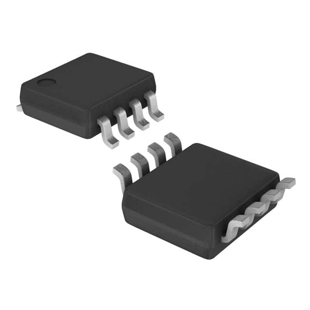
Encyclopedia Entry: 74AUC2G125DCURG4
Product Overview
- Category: Integrated Circuit (IC)
- Use: Logic Buffer/Driver
- Characteristics: High-speed, low-power, dual-channel buffer/driver
- Package: SOT-353 (5-pin package)
- Essence: The 74AUC2G125DCURG4 is a versatile logic buffer/driver IC that provides high-speed signal buffering and driving capabilities in a compact package.
- Packaging/Quantity: Available in tape and reel packaging with 3000 units per reel.
Specifications
- Supply Voltage Range: 0.8V to 3.6V
- Input Voltage Range: -0.5V to VCC + 0.5V
- Output Voltage Range: 0V to VCC
- Operating Temperature Range: -40°C to +85°C
- Propagation Delay: 1.9ns (typical)
- Output Drive Capability: ±24mA
Detailed Pin Configuration
The 74AUC2G125DCURG4 IC has the following pin configuration:
___________
      |           |
   1 -| A         |
   2 -| Y         |
   3 -| GND       |
   4 -| B         |
   5 -| VCC       |
      |___________|
Pin Description: - Pin 1 (A): Input A - Pin 2 (Y): Output Y - Pin 3 (GND): Ground - Pin 4 (B): Input B - Pin 5 (VCC): Power Supply
Functional Features
- Dual-channel buffer/driver with independent input and output pins.
- Provides voltage level shifting and signal buffering capabilities.
- High-speed operation suitable for applications requiring fast signal propagation.
- Low-power consumption, making it ideal for battery-powered devices.
- Supports a wide supply voltage range, allowing compatibility with various systems.
Advantages and Disadvantages
Advantages: - Compact package size enables space-saving designs. - High-speed operation improves overall system performance. - Low-power consumption extends battery life in portable devices. - Wide supply voltage range enhances versatility.
Disadvantages: - Limited output drive capability may not be suitable for high-current applications. - Sensitive to electrostatic discharge (ESD), requiring proper handling during assembly.
Working Principles
The 74AUC2G125DCURG4 is designed to buffer and drive logic signals. It operates by receiving input signals at pins A and B, and then amplifying and shifting the voltage levels to match the desired output logic levels. The buffered output is available at pin Y, which can be connected to other components or subsystems.
Detailed Application Field Plans
The 74AUC2G125DCURG4 IC finds applications in various fields, including but not limited to: 1. Consumer electronics: Mobile phones, tablets, and digital cameras. 2. Computer peripherals: USB interfaces, memory modules, and display controllers. 3. Industrial automation: Sensor interfacing, motor control, and PLCs. 4. Automotive electronics: Infotainment systems, dashboard displays, and lighting controls. 5. Internet of Things (IoT): Smart home devices, wearable technology, and wireless sensors.
Detailed and Complete Alternative Models
- 74LVC2G125DCURG4: Similar dual-channel buffer/driver with 5-pin SOT-353 package.
- SN74LVC2G125DCUR: Dual-channel buffer/driver from Texas Instruments with similar specifications.
- NC7SZ125P5X: Single-channel buffer/driver with 5-pin SC-70 package from Fairchild Semiconductor.
Note: The above alternative models are provided for reference and may have slight differences in specifications or pin configuration. It is recommended to refer to the respective datasheets for detailed information.
Word count: 498 words
Lista 10 Vanliga frågor och svar relaterade till tillämpningen av 74AUC2G125DCURG4 i tekniska lösningar
Sure! Here are 10 common questions and answers related to the application of 74AUC2G125DCURG4 in technical solutions:
Q: What is the 74AUC2G125DCURG4? A: The 74AUC2G125DCURG4 is a dual bus buffer gate with 3-state outputs, designed for low-voltage applications.
Q: What is the operating voltage range of the 74AUC2G125DCURG4? A: The operating voltage range of the 74AUC2G125DCURG4 is typically between 0.8V and 3.6V.
Q: What is the maximum output current of the 74AUC2G125DCURG4? A: The maximum output current of the 74AUC2G125DCURG4 is typically around 24mA.
Q: Can the 74AUC2G125DCURG4 be used in high-speed applications? A: Yes, the 74AUC2G125DCURG4 is designed for high-speed operation, making it suitable for various applications.
Q: What is the package type of the 74AUC2G125DCURG4? A: The 74AUC2G125DCURG4 comes in a small SOT-353 package, which is ideal for space-constrained designs.
Q: Is the 74AUC2G125DCURG4 compatible with other logic families? A: Yes, the 74AUC2G125DCURG4 is compatible with both CMOS and TTL logic families.
Q: Can the 74AUC2G125DCURG4 handle bidirectional data flow? A: Yes, the 74AUC2G125DCURG4 supports bidirectional data flow, making it suitable for applications requiring data input and output.
Q: What is the typical propagation delay of the 74AUC2G125DCURG4? A: The typical propagation delay of the 74AUC2G125DCURG4 is around 1.5ns.
Q: Does the 74AUC2G125DCURG4 have built-in ESD protection? A: Yes, the 74AUC2G125DCURG4 has built-in ESD protection, ensuring robustness against electrostatic discharge.
Q: What are some common applications of the 74AUC2G125DCURG4? A: The 74AUC2G125DCURG4 can be used in various applications such as level shifting, signal buffering, bus interfacing, and more.
Please note that the answers provided here are general and may vary depending on specific datasheet specifications and application requirements.


