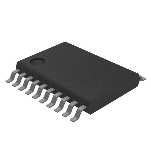
CD74ACT273PWR
Basic Information Overview
- Category: Integrated Circuit (IC)
- Use: Flip-Flop
- Characteristics: High-speed, low-power consumption
- Package: TSSOP (Thin Shrink Small Outline Package)
- Essence: D-type positive-edge-triggered flip-flop
- Packaging/Quantity: Tape and Reel, 2500 units per reel
Specifications
- Supply Voltage Range: 2V to 6V
- Input Voltage Range: 0V to VCC
- Operating Temperature Range: -40°C to +85°C
- Output Current: ±24mA
- Propagation Delay: 5.5ns (typical)
Detailed Pin Configuration
The CD74ACT273PWR has a total of 20 pins. The pin configuration is as follows:
- CLR (Clear)
- D0 (Data Input 0)
- D1 (Data Input 1)
- D2 (Data Input 2)
- D3 (Data Input 3)
- D4 (Data Input 4)
- D5 (Data Input 5)
- D6 (Data Input 6)
- D7 (Data Input 7)
- GND (Ground)
- Q7 (Output 7)
- Q6 (Output 6)
- Q5 (Output 5)
- Q4 (Output 4)
- Q3 (Output 3)
- Q2 (Output 2)
- Q1 (Output 1)
- Q0 (Output 0)
- CLK (Clock)
- VCC (Supply Voltage)
Functional Features
- Positive-edge-triggered flip-flop with asynchronous clear capability
- High-speed operation, suitable for applications requiring quick data storage
- Low power consumption, making it ideal for battery-powered devices
- Wide supply voltage range allows compatibility with various systems
Advantages and Disadvantages
Advantages: - High-speed operation enables efficient data storage - Low power consumption prolongs battery life in portable devices - Wide supply voltage range provides flexibility in system design
Disadvantages: - Limited number of outputs (8 in total) - Asynchronous clear capability may introduce potential hazards if not used properly
Working Principles
The CD74ACT273PWR is a D-type positive-edge-triggered flip-flop. It stores data on the rising edge of the clock signal. The asynchronous clear input allows for immediate resetting of the flip-flop. The device operates at high speed while consuming low power.
Detailed Application Field Plans
The CD74ACT273PWR can be used in various applications, including but not limited to: 1. Digital counters 2. Data storage systems 3. Address decoding circuits 4. Register banks 5. State machines
Detailed and Complete Alternative Models
- SN74ACT273: Similar functionality and specifications, different package (DIP)
- MC74ACT273: Comparable features, alternative manufacturer (Motorola)
- 74HC273: CMOS version with similar functionality, lower power consumption
These alternative models provide similar functionality to the CD74ACT273PWR and can be considered as substitutes based on specific requirements.
Word count: 320 words
Lista 10 Vanliga frågor och svar relaterade till tillämpningen av CD74ACT273PWR i tekniska lösningar
Sure! Here are 10 common questions and answers related to the application of CD74ACT273PWR:
Q: What is CD74ACT273PWR? A: CD74ACT273PWR is a type of octal D-type flip-flop integrated circuit (IC) that can store and manipulate digital data.
Q: What is the purpose of CD74ACT273PWR? A: CD74ACT273PWR is commonly used in digital systems to store and synchronize data, control registers, and perform various sequential logic functions.
Q: What is the operating voltage range for CD74ACT273PWR? A: CD74ACT273PWR operates within a voltage range of 2V to 6V.
Q: How many flip-flops are there in CD74ACT273PWR? A: CD74ACT273PWR consists of 8 individual flip-flops, making it an octal (8-bit) device.
Q: What is the maximum clock frequency supported by CD74ACT273PWR? A: CD74ACT273PWR can typically operate at clock frequencies up to 100 MHz.
Q: Can CD74ACT273PWR be cascaded to increase the number of flip-flops? A: Yes, multiple CD74ACT273PWR ICs can be cascaded together to increase the number of flip-flops and create larger storage capacities.
Q: Does CD74ACT273PWR have any built-in output enable or reset functionality? A: No, CD74ACT273PWR does not have built-in output enable or reset features. Additional logic gates or external components may be required for such functionalities.
Q: What is the power consumption of CD74ACT273PWR? A: CD74ACT273PWR has relatively low power consumption, typically around a few milliwatts.
Q: Can CD74ACT273PWR operate in both synchronous and asynchronous modes? A: Yes, CD74ACT273PWR can be used in both synchronous and asynchronous applications, depending on the design requirements.
Q: What are some typical applications of CD74ACT273PWR? A: CD74ACT273PWR is commonly used in microprocessors, memory systems, data storage devices, digital counters, and various other digital circuits that require data storage and manipulation capabilities.
Please note that these answers are general and may vary based on specific datasheet specifications and application requirements.


