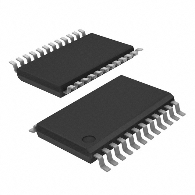
CDCE949PWR
Overview
CDCE949PWR is a product belonging to the category of integrated circuits. It is commonly used in electronic devices for clock generation and distribution purposes. This integrated circuit offers various characteristics that make it suitable for a wide range of applications. The package of CDCE949PWR consists of a small form factor, allowing for easy integration into electronic systems. Its essence lies in its ability to generate and distribute precise clock signals, which are essential for synchronizing different components within a system. CDCE949PWR is typically available in packages containing multiple units.
Specifications and Parameters
- Input Voltage Range: 2.5V to 3.6V
- Output Frequency Range: 1MHz to 200MHz
- Number of Outputs: 9
- Operating Temperature Range: -40°C to +85°C
- Package Type: TSSOP
Pin Configuration
The pin configuration of CDCE949PWR is as follows:
- VDD
- GND
- XIN
- XOUT
- CLK0_OUT
- CLK1_OUT
- CLK2_OUT
- CLK3_OUT
- CLK4_OUT
- CLK5_OUT
- CLK6_OUT
- CLK7_OUT
- CLK8_OUT
- SDA
- SCL
- OE
Functional Characteristics
CDCE949PWR offers the following functional characteristics:
- Clock Generation: It can generate up to nine independent clock signals with precise frequency control.
- Clock Distribution: The generated clock signals can be distributed to various components within a system.
- Programmability: The device allows for flexible programming of output frequencies and other parameters.
- Low Jitter: CDCE949PWR ensures low jitter performance, resulting in accurate timing synchronization.
- I2C Interface: It features an I2C interface for easy configuration and control.
Advantages and Disadvantages
Advantages of CDCE949PWR include:
- Versatility: It can be used in a wide range of electronic devices requiring clock generation and distribution.
- Precision: The device offers precise frequency control, ensuring accurate timing synchronization.
- Programmability: Its programmable nature allows for customization according to specific requirements.
Disadvantages of CDCE949PWR include:
- Complexity: The device may require some expertise to configure and utilize effectively.
- Power Consumption: CDCE949PWR consumes power during operation, which should be considered in low-power applications.
Applicable Range of Products
CDCE949PWR is applicable in various electronic devices that require clock generation and distribution. It finds use in telecommunications equipment, networking devices, consumer electronics, and industrial automation systems, among others.
Working Principles
The working principle of CDCE949PWR involves taking an input clock signal and using internal PLLs (Phase-Locked Loops) to generate multiple output clock signals with precise frequencies. These output clocks can then be distributed to different components within a system, ensuring proper synchronization.
Detailed Application Field Plans
CDCE949PWR can be utilized in the following application fields:
- Telecommunications: Used in base stations, routers, and switches for clock synchronization.
- Consumer Electronics: Integrated into audio/video equipment, gaming consoles, and set-top boxes for timing control.
- Industrial Automation: Employed in PLCs (Programmable Logic Controllers), motor control systems, and robotics for precise timing.
- Automotive Electronics: Utilized in infotainment systems, ADAS (Advanced Driver Assistance Systems), and engine control units for synchronization purposes.
- Medical Devices: Integrated into medical imaging equipment, patient monitoring systems, and diagnostic instruments for accurate timing.
Detailed Alternative Models
Some alternative models to CDCE949PWR include:
- CDCE913PWR
- CDCE925PWR
- CDCE937PWR
- CDCE961PWR
- CDCE973PWR
5 Common Technical Questions and Answers
Q: What is the maximum output frequency of CDCE949PWR? A: The maximum output frequency is 200MHz.
Q: Can CDCE949PWR operate with a supply voltage below 2.5V? A: No, the input voltage range should be between 2.5V and 3.6V.
Q: How many clock outputs does CDCE949PWR provide? A: It provides nine clock outputs.
Q: Is CDCE949PWR compatible with I2C interface? A: Yes, it features an I2C interface for configuration and control.
Q: What is the operating temperature range of CDCE949PWR? A: CDCE949PWR can operate within a temperature range of -40°C to +85°C.
This concludes


