

SN74ABT16245ADLR
Product Overview
- Category: Integrated Circuit (IC)
- Use: Bus Transceiver
- Characteristics: High-speed, bidirectional, 16-bit transceiver
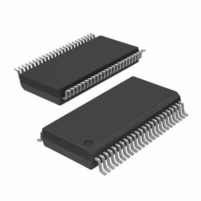
- Package: TSSOP (Thin Shrink Small Outline Package)
- Essence: Facilitates bidirectional data transfer between two buses with different voltage levels
- Packaging/Quantity: Tape and Reel, 2500 units per reel
Specifications
- Supply Voltage Range: 4.5V to 5.5V
- Input Voltage Range: 0V to VCC
- Output Voltage Range: 0V to VCC
- Operating Temperature Range: -40°C to +85°C
- Propagation Delay Time: 3.8ns (Max)
- Output Current: ±12mA
- ESD Protection: >2000V
Detailed Pin Configuration
The SN74ABT16245ADLR has a total of 48 pins, which are divided into four groups:
Group A (Pins 1-12)
- Pins 1-4: Port A Data Inputs/Outputs (A1-A4)
- Pins 5-8: Port B Data Inputs/Outputs (B1-B4)
- Pins 9-12: Control Inputs (DIR, OE1, OE2, GND)
Group B (Pins 13-24)
- Pins 13-16: Port A Data Inputs/Outputs (A5-A8)
- Pins 17-20: Port B Data Inputs/Outputs (B5-B8)
- Pins 21-24: Control Inputs (DIR, OE1, OE2, VCC)
Group C (Pins 25-36)
- Pins 25-28: Port A Data Inputs/Outputs (A9-A12)
- Pins 29-32: Port B Data Inputs/Outputs (B9-B12)
- Pins 33-36: Control Inputs (DIR, OE1, OE2, GND)
Group D (Pins 37-48)
- Pins 37-40: Port A Data Inputs/Outputs (A13-A16)
- Pins 41-44: Port B Data Inputs/Outputs (B13-B16)
- Pins 45-48: Control Inputs (DIR, OE1, OE2, VCC)
Functional Features
- Bidirectional data transfer between two buses with different voltage levels
- High-speed operation for efficient data transmission
- Non-inverting outputs for accurate signal reproduction
- Output enable and direction control for flexible bus management
- ESD protection for enhanced reliability
Advantages and Disadvantages
Advantages
- Enables seamless communication between buses with different voltage levels
- High-speed operation minimizes data transfer delays
- Flexible control options for efficient bus management
- Robust ESD protection ensures reliable performance
Disadvantages
- Limited to 16-bit data transfer
- Requires careful consideration of voltage compatibility between buses
Working Principles
The SN74ABT16245ADLR is a bidirectional bus transceiver that facilitates data transfer between two buses operating at different voltage levels. It utilizes non-inverting outputs to accurately reproduce the input signals. The direction control pin (DIR) determines the data flow direction, while the output enable pins (OE1 and OE2) enable or disable the outputs.
When the DIR pin is set to logic high, data flows from Port A to Port B. Conversely, when the DIR pin is set to logic low, data flows from Port B to Port A. The output enable pins allow the user to enable or disable the outputs as needed.
Detailed Application Field Plans
The SN74ABT16245ADLR is commonly used in various applications that require bidirectional data transfer between buses with different voltage levels. Some of the typical application fields include:
- Industrial Automation: Facilitating communication between control systems operating at different voltage levels.
- Telecommunications: Enabling data exchange between different network interfaces.
- Automotive Electronics: Connecting various subsystems with varying voltage requirements.
- Computer Peripherals: Interfacing between different components within a computer system.
Detailed and Complete Alternative Models
- SN74ABT16245A: Similar to SN74ABT16245ADLR, but without the TSSOP package option.
- SN74LVC16245A: A low-voltage version of the transceiver with a wider supply voltage range.
- SN74HCT245: A TTL-compatible alternative for applications requiring compatibility with TTL logic levels.
These alternative models offer similar functionality and can be considered based on specific application requirements.
Word count: 570 words
Lista 10 Vanliga frågor och svar relaterade till tillämpningen av SN74ABT16245ADLR i tekniska lösningar
Sure! Here are 10 common questions and answers related to the application of SN74ABT16245ADLR in technical solutions:
Q: What is SN74ABT16245ADLR? A: SN74ABT16245ADLR is a 16-bit bus transceiver with 3-state outputs, commonly used for bidirectional data transfer between different voltage levels.
Q: What is the operating voltage range of SN74ABT16245ADLR? A: The operating voltage range of SN74ABT16245ADLR is typically between 4.5V and 5.5V.
Q: Can SN74ABT16245ADLR handle level shifting between different voltage domains? A: Yes, SN74ABT16245ADLR is designed to handle level shifting between different voltage domains, making it suitable for interfacing between devices operating at different voltages.
Q: How many channels does SN74ABT16245ADLR have? A: SN74ABT16245ADLR has 16 bidirectional channels, allowing for simultaneous data transfer on multiple lines.
Q: What is the maximum data transfer rate supported by SN74ABT16245ADLR? A: SN74ABT16245ADLR supports high-speed data transfer rates up to 100 MHz.
Q: Can SN74ABT16245ADLR be used in both parallel and serial communication systems? A: Yes, SN74ABT16245ADLR can be used in both parallel and serial communication systems, depending on the application requirements.
Q: Does SN74ABT16245ADLR have built-in protection features? A: Yes, SN74ABT16245ADLR has built-in ESD (Electrostatic Discharge) protection, which helps safeguard the device from damage during handling and operation.
Q: Can SN74ABT16245ADLR be used in automotive applications? A: Yes, SN74ABT16245ADLR is qualified for automotive applications and meets the necessary industry standards.
Q: What is the power supply current consumption of SN74ABT16245ADLR? A: The power supply current consumption of SN74ABT16245ADLR varies depending on the operating conditions but typically ranges from 10mA to 20mA.
Q: Are there any specific layout considerations when using SN74ABT16245ADLR? A: Yes, it is recommended to follow the layout guidelines provided in the datasheet to ensure proper signal integrity and minimize noise coupling between channels.
Please note that these answers are general and may vary based on specific application requirements and the manufacturer's recommendations.