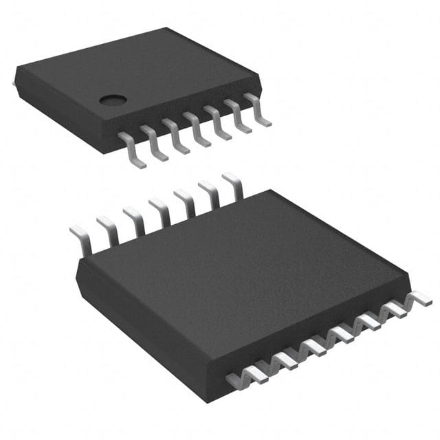
SN74AHCT74MPWREP
Product Overview
- Category: Integrated Circuit (IC)
- Use: Flip-Flop
- Characteristics: High-speed, low-power, dual D-type positive-edge-triggered flip-flop
- Package: TSSOP (Thin Shrink Small Outline Package)
- Essence: Reliable and efficient digital logic component
- Packaging/Quantity: Tape and Reel, 2500 units per reel
Specifications
- Supply Voltage Range: 4.5V to 5.5V
- High-Level Input Voltage: 2V
- Low-Level Input Voltage: 0.8V
- High-Level Output Voltage: 4V
- Low-Level Output Voltage: 0.4V
- Maximum Operating Frequency: 100MHz
- Propagation Delay Time: 7ns
- Operating Temperature Range: -40°C to +85°C
Detailed Pin Configuration
The SN74AHCT74MPWREP has a total of 14 pins, which are labeled as follows:
- CLR (Clear) - Active LOW clear input
- D (Data) - Data input
- CLK (Clock) - Clock input
- PR (Preset) - Active LOW preset input
- Q (Output) - Complementary output
- Q̅ (Output) - Non-complementary output
- GND (Ground) - Ground reference
- Q̅ (Output) - Non-complementary output
- Q (Output) - Complementary output
- VCC (Supply Voltage) - Positive supply voltage
- D (Data) - Data input
- CLK (Clock) - Clock input
- PR (Preset) - Active LOW preset input
- CLR (Clear) - Active LOW clear input
Functional Features
- Dual D-type positive-edge-triggered flip-flop
- High-speed operation with low power consumption
- Asynchronous clear and preset inputs for easy initialization
- Complementary and non-complementary outputs for versatile applications
- Wide operating voltage range for compatibility with various systems
Advantages and Disadvantages
Advantages: - High-speed operation allows for efficient data processing - Low-power consumption reduces energy requirements - Dual flip-flop design provides flexibility in circuit design - Asynchronous clear and preset inputs simplify initialization process
Disadvantages: - Limited operating frequency compared to some other flip-flops - Requires careful handling due to small package size
Working Principles
The SN74AHCT74MPWREP is a dual D-type positive-edge-triggered flip-flop. It operates based on the rising edge of the clock signal (CLK). When the CLK input transitions from LOW to HIGH, the data present at the D input is transferred to the Q and Q̅ outputs. The complementary outputs provide both inverted and non-inverted versions of the input data.
The flip-flop can be cleared using the CLR input, which is active LOW. When CLR is brought LOW, both Q and Q̅ outputs are forced to logic LOW state. Similarly, the PR input (active LOW) can be used to preset the flip-flop outputs to logic HIGH state.
Detailed Application Field Plans
The SN74AHCT74MPWREP is widely used in digital systems where reliable and efficient flip-flop functionality is required. Some common application areas include:
- Microprocessors and microcontrollers
- Data storage and retrieval systems
- Communication systems
- Digital signal processing
- Timing and synchronization circuits
Detailed and Complete Alternative Models
- SN74AHCT74PWR - Similar specifications and pin configuration, but in a different package (TSSOP)
- MC74HC74AN - Comparable functionality and characteristics, but in a different logic family (HC)
- CD4013BE - Dual D-type flip-flop with similar features, but in a different package (DIP)
These alternative models can be considered based on specific requirements and availability.
Word count: 500 words
Lista 10 Vanliga frågor och svar relaterade till tillämpningen av SN74AHCT74MPWREP i tekniska lösningar
Sure! Here are 10 common questions and answers related to the application of SN74AHCT74MPWREP in technical solutions:
Q: What is SN74AHCT74MPWREP? A: SN74AHCT74MPWREP is a dual positive-edge-triggered D-type flip-flop with clear and preset, which is commonly used in digital circuits.
Q: What is the operating voltage range for SN74AHCT74MPWREP? A: The operating voltage range for SN74AHCT74MPWREP is typically between 4.5V and 5.5V.
Q: What is the maximum clock frequency supported by SN74AHCT74MPWREP? A: SN74AHCT74MPWREP can support clock frequencies up to 24 MHz.
Q: How many flip-flops are there in SN74AHCT74MPWREP? A: SN74AHCT74MPWREP consists of two independent flip-flops.
Q: What is the purpose of the clear and preset inputs in SN74AHCT74MPWREP? A: The clear input allows you to reset the flip-flop to a known state, while the preset input allows you to set the flip-flop to a specific state.
Q: Can SN74AHCT74MPWREP be used in both synchronous and asynchronous applications? A: Yes, SN74AHCT74MPWREP can be used in both synchronous and asynchronous applications.
Q: What is the output drive capability of SN74AHCT74MPWREP? A: SN74AHCT74MPWREP has a typical output drive capability of ±8 mA.
Q: Is SN74AHCT74MPWREP compatible with other logic families? A: Yes, SN74AHCT74MPWREP is compatible with a wide range of logic families, including TTL, CMOS, and LVTTL.
Q: Can SN74AHCT74MPWREP be used in high-speed applications? A: Yes, SN74AHCT74MPWREP is designed for high-speed operation and can be used in various high-speed applications.
Q: What are some typical applications of SN74AHCT74MPWREP? A: SN74AHCT74MPWREP is commonly used in applications such as data storage, counters, registers, and general-purpose flip-flop circuits.
Please note that the answers provided here are general and may vary depending on specific design considerations and requirements.


