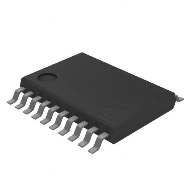
SN74HC273PWT
Product Overview
- Category: Integrated Circuit
- Use: Flip-Flop
- Characteristics: High-speed, low-power consumption
- Package: TSSOP-20
- Essence: D-type Positive-Edge-Triggered Flip-Flop
- Packaging/Quantity: Tape and Reel, 2500 pieces per reel
Specifications
- Supply Voltage Range: 2V to 6V
- High-Level Input Voltage: 2V to VCC
- Low-Level Input Voltage: GND to 0.8V
- High-Level Output Current: -4mA
- Low-Level Output Current: 4mA
- Operating Temperature Range: -40°C to +85°C
Detailed Pin Configuration
- CP (Clock Pulse) - Clock input for flip-flop operation.
- D (Data) - Data input to be stored in the flip-flop.
- Q (Output) - Output of the flip-flop.
- GND (Ground) - Ground reference voltage.
- Q̅ (Complementary Output) - Complementary output of the flip-flop.
- D̅ (Complementary Data) - Complementary data input to be stored in the flip-flop.
- MR (Master Reset) - Resets the flip-flop to a known state.
- PR (Preset) - Sets the flip-flop to a known state.
- Q̅ (Complementary Output) - Complementary output of the flip-flop.
- Q (Output) - Output of the flip-flop.
- D (Data) - Data input to be stored in the flip-flop.
- CP (Clock Pulse) - Clock input for flip-flop operation.
- GND (Ground) - Ground reference voltage.
- Q̅ (Complementary Output) - Complementary output of the flip-flop.
- D̅ (Complementary Data) - Complementary data input to be stored in the flip-flop.
- MR (Master Reset) - Resets the flip-flop to a known state.
- PR (Preset) - Sets the flip-flop to a known state.
- Q̅ (Complementary Output) - Complementary output of the flip-flop.
- Q (Output) - Output of the flip-flop.
- VCC (Supply Voltage) - Positive supply voltage.
Functional Features
- Positive-edge-triggered D-type flip-flop with asynchronous reset and preset capability.
- High-speed operation, suitable for applications requiring fast data storage.
- Low-power consumption, making it ideal for battery-powered devices.
- Can be cascaded to create larger storage registers or counters.
- Provides complementary outputs for easy integration into digital systems.
Advantages
- High-speed operation allows for efficient data storage and retrieval.
- Low-power consumption extends battery life in portable devices.
- Versatile functionality with reset and preset capabilities.
- Compact package size enables space-saving designs.
- Complementary outputs simplify system integration.
Disadvantages
- Limited number of flip-flops per package may restrict the size of storage registers or counters.
- Requires careful handling during assembly due to small package size.
- Sensitive to electrostatic discharge (ESD), necessitating proper ESD precautions during handling and usage.
Working Principles
The SN74HC273PWT is a positive-edge-triggered D-type flip-flop. It stores data at the rising edge of the clock pulse (CP) input. The data input (D) is transferred to the output (Q) when the clock pulse rises from low to high. The flip-flop can be asynchronously reset using the master reset (MR) input or set to a known state using the preset (PR) input. The complementary outputs (Q̅ and Q̅) provide inverted versions of the main output (Q).
Detailed Application Field Plans
The SN74HC273PWT is commonly used in various digital systems, including:
- Microcontrollers and microprocessors
- Communication systems
- Data storage devices
- Industrial automation equipment
- Automotive electronics
- Consumer electronics
Detailed and Complete Alternative Models
- SN74HC374PWT - Octal D-type flip-flop with 3-state outputs
- SN74HC574PWT - Octal D-type flip-flop with 3-state outputs and power-up reset
- SN74HC377PWT - Octal D-type flip-flop with clock enable
These alternative models offer similar functionality to the SN74HC273PWT but may have additional features or different pin configurations.
Word count: 526 words
Lista 10 Vanliga frågor och svar relaterade till tillämpningen av SN74HC273PWT i tekniska lösningar
Sure! Here are 10 common questions and answers related to the application of SN74HC273PWT in technical solutions:
Q: What is SN74HC273PWT? A: SN74HC273PWT is a type of integrated circuit (IC) commonly used as an octal D-type flip-flop with reset.
Q: What are the main features of SN74HC273PWT? A: The main features of SN74HC273PWT include 8 flip-flops, asynchronous reset capability, high-speed operation, and compatibility with various logic families.
Q: How can I use SN74HC273PWT in my circuit design? A: SN74HC273PWT can be used to store and manipulate binary data in applications such as counters, registers, and state machines.
Q: What is the power supply voltage range for SN74HC273PWT? A: SN74HC273PWT operates within a power supply voltage range of 2V to 6V.
Q: Can SN74HC273PWT handle high-speed data transfers? A: Yes, SN74HC273PWT is designed for high-speed operation and can handle data transfers at frequencies up to several hundred megahertz.
Q: Does SN74HC273PWT have any built-in protection features? A: SN74HC273PWT has built-in diode clamps on its inputs to protect against electrostatic discharge (ESD).
Q: Can I cascade multiple SN74HC273PWT ICs together? A: Yes, you can cascade multiple SN74HC273PWT ICs to increase the number of flip-flops in your circuit.
Q: What is the maximum current that SN74HC273PWT can source or sink? A: SN74HC273PWT can source or sink up to 6mA of current per output pin.
Q: Is SN74HC273PWT compatible with other logic families? A: Yes, SN74HC273PWT is compatible with a wide range of logic families, including TTL, CMOS, and LVTTL.
Q: Where can I find more information about using SN74HC273PWT in my technical solution? A: You can refer to the datasheet provided by the manufacturer for detailed information on the electrical characteristics, timing diagrams, and application examples of SN74HC273PWT.


