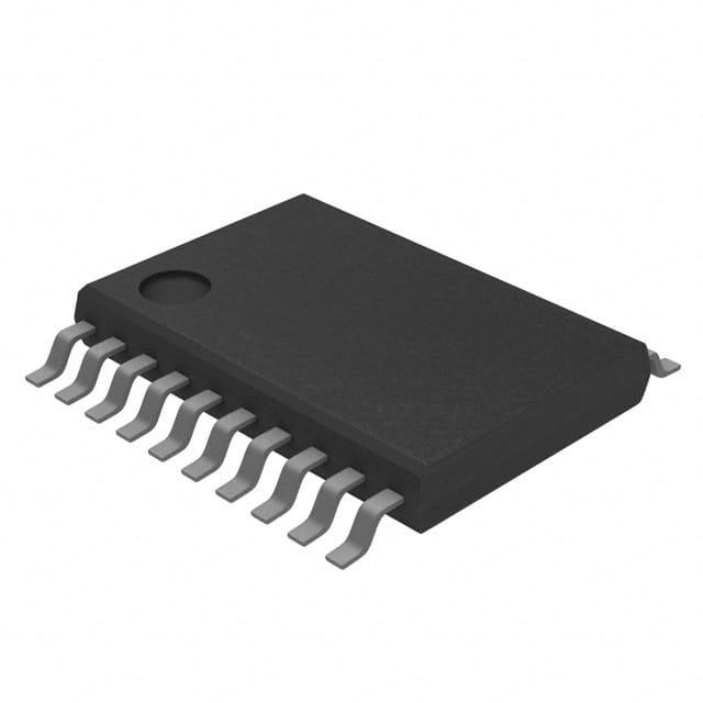
SN74LVC374APWT
Product Overview
- Category: Integrated Circuit (IC)
- Use: Flip-Flop
- Characteristics: Low Voltage, CMOS Technology
- Package: TSSOP-20
- Essence: D-Type Transparent Latch
- Packaging/Quantity: Tape and Reel, 2500 pieces per reel
Specifications
- Supply Voltage Range: 1.65V to 5.5V
- High-Level Input Voltage: 2V to VCC + 0.5V
- Low-Level Input Voltage: -0.5V to 0.8V
- High-Level Output Voltage: VCC - 0.4V
- Low-Level Output Voltage: 0.4V
- Maximum Operating Frequency: 80MHz
- Number of Flip-Flops: 8
Detailed Pin Configuration
The SN74LVC374APWT has a total of 20 pins. The pin configuration is as follows:
- Pin 1: Data Input (D0)
- Pin 2: Data Input (D1)
- Pin 3: Data Input (D2)
- Pin 4: Data Input (D3)
- Pin 5: Data Input (D4)
- Pin 6: Data Input (D5)
- Pin 7: Data Input (D6)
- Pin 8: Data Input (D7)
- Pin 9: Clock Input (CLK)
- Pin 10: Output Enable (OE)
- Pin 11: Master Reset (MR)
- Pin 12: Q Output (Q0)
- Pin 13: Q Output (Q1)
- Pin 14: Q Output (Q2)
- Pin 15: Q Output (Q3)
- Pin 16: Q Output (Q4)
- Pin 17: Q Output (Q5)
- Pin 18: Q Output (Q6)
- Pin 19: Q Output (Q7)
- Pin 20: Ground (GND)
Functional Features
The SN74LVC374APWT is a D-Type Transparent Latch with 8 flip-flops. It operates at low voltage and utilizes CMOS technology. The latch allows data to be stored and transferred based on the clock input. The output enable pin controls the output state, while the master reset pin resets all flip-flops to a known state.
Advantages and Disadvantages
Advantages: - Low voltage operation - High-speed performance - Compact package size - Easy integration into various circuits
Disadvantages: - Limited number of flip-flops - Not suitable for high-power applications
Working Principles
The SN74LVC374APWT works by latching the input data when the clock signal transitions from low to high. The latched data is then available at the output pins. The output enable pin can be used to disable the outputs, allowing for easy control of the data flow. The master reset pin resets all flip-flops to a low state when activated.
Detailed Application Field Plans
The SN74LVC374APWT is commonly used in various digital systems and applications, including:
- Microcontrollers
- Data storage devices
- Communication systems
- Industrial automation
- Automotive electronics
Detailed and Complete Alternative Models
Some alternative models that can be considered as alternatives to the SN74LVC374APWT are:
- SN74LVCH374APW - Similar characteristics and pin configuration, but operates at higher voltage levels.
- CD74HCT374E - TTL logic family alternative with similar functionality.
- MC74VHC374DTR2G - High-speed CMOS alternative with improved performance.
These alternatives provide similar functionality and can be used as replacements depending on specific requirements.
Word count: 320 words
Lista 10 Vanliga frågor och svar relaterade till tillämpningen av SN74LVC374APWT i tekniska lösningar
Sure! Here are 10 common questions and answers related to the application of SN74LVC374APWT:
Q: What is SN74LVC374APWT? A: SN74LVC374APWT is a type of octal D-type flip-flop integrated circuit (IC) that can be used in various technical solutions.
Q: What is the purpose of SN74LVC374APWT? A: SN74LVC374APWT is used to store and transfer data in digital systems. It can be used for latching, buffering, and synchronization purposes.
Q: What is the voltage range supported by SN74LVC374APWT? A: SN74LVC374APWT supports a voltage range of 1.65V to 5.5V, making it compatible with a wide range of digital systems.
Q: How many flip-flops are there in SN74LVC374APWT? A: SN74LVC374APWT contains 8 flip-flops, making it an octal (8-bit) device.
Q: Can SN74LVC374APWT be used for both input and output operations? A: Yes, SN74LVC374APWT can be used as both an input and output device. It has separate input and output pins for each flip-flop.
Q: What is the maximum clock frequency supported by SN74LVC374APWT? A: SN74LVC374APWT can operate at a maximum clock frequency of 100 MHz, allowing for high-speed data transfer.
Q: Does SN74LVC374APWT have any built-in protection features? A: Yes, SN74LVC374APWT has built-in protection against electrostatic discharge (ESD) and excessive power dissipation.
Q: Can SN74LVC374APWT be cascaded to increase the number of flip-flops? A: Yes, multiple SN74LVC374APWT ICs can be cascaded together to increase the number of flip-flops in a system.
Q: What is the power supply voltage required for SN74LVC374APWT? A: SN74LVC374APWT requires a power supply voltage between 2.7V and 3.6V for proper operation.
Q: Are there any specific application notes or reference designs available for SN74LVC374APWT? A: Yes, Texas Instruments provides application notes and reference designs that can help in implementing SN74LVC374APWT in various technical solutions.
Please note that these answers are general and may vary depending on the specific requirements and use cases. It's always recommended to refer to the datasheet and documentation provided by the manufacturer for accurate information.


