

Encyclopedia Entry: 74VHCT540AFT
Product Overview
Category
The 74VHCT540AFT belongs to the category of integrated circuits (ICs) and specifically falls under the family of VHCT series ICs.
Use
This IC is commonly used as a buffer or line driver in digital systems. It is designed to provide voltage level shifting and signal amplification capabilities, making it suitable for various applications in electronic devices.
Characteristics
- Voltage Compatibility: The 74VHCT540AFT operates at a wide range of supply voltages, typically between 2.0V and 5.5V.
- High-Speed Operation: This IC offers fast switching speeds, enabling efficient data transmission in high-frequency applications.
- Low Power Consumption: With its low power dissipation characteristics, the 74VHCT540AFT helps conserve energy in electronic systems.
- ESD Protection: The IC incorporates Electrostatic Discharge (ESD) protection features, enhancing its reliability and durability.
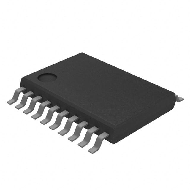
Package and Quantity
The 74VHCT540AFT is available in a small-outline integrated circuit (SOIC) package. It is typically sold in reels containing a specified quantity of ICs, such as 250 or 1000 units per reel.
Specifications
- Logic Family: VHCT
- Number of Channels: 8
- Input Voltage Range: 0V to VCC
- Output Voltage Range: 0V to VCC
- Maximum Supply Voltage (VCC): 5.5V
- Minimum Supply Voltage (VCC): 2.0V
- Operating Temperature Range: -40°C to +85°C
- Propagation Delay Time: <10 ns
Pin Configuration
The 74VHCT540AFT has a total of 20 pins, which are assigned specific functions as follows:
- GND: Ground
- A1: Input A1
- Y1: Output Y1
- A2: Input A2
- Y2: Output Y2
- A3: Input A3
- Y3: Output Y3
- A4: Input A4
- Y4: Output Y4
- OE: Output Enable
- Y5: Output Y5
- A5: Input A5
- Y6: Output Y6
- A6: Input A6
- Y7: Output Y7
- A7: Input A7
- Y8: Output Y8
- VCC: Supply Voltage
- GND: Ground
- NC: No Connection
Functional Features
- Buffer/Line Driver: The 74VHCT540AFT acts as a buffer or line driver, providing voltage level shifting and signal amplification capabilities.
- Output Enable (OE) Control: The IC includes an OE pin that allows the user to enable or disable the outputs, providing flexibility in system design.
- High-Speed Operation: With its fast switching speeds, this IC ensures efficient data transmission in high-frequency applications.
Advantages and Disadvantages
Advantages: - Wide supply voltage range allows compatibility with various systems. - Low power consumption helps conserve energy. - ESD protection enhances reliability. - Fast switching speeds enable efficient data transmission.
Disadvantages: - Limited number of channels (8) may not be suitable for applications requiring a higher channel count. - Propagation delay time may affect timing-sensitive applications.
Working Principles
The 74VHCT540AFT operates by receiving input signals on the designated input pins (A1-A7). These signals are then amplified and shifted to the corresponding output pins (Y1-Y8) based on the logic levels. The OE pin controls the output enable/disable functionality, allowing the user to control the state of the outputs.
Application Field Plans
The 74VHCT540AFT finds applications in various electronic systems, including but not limited to: - Data communication systems - Microcontrollers and microprocessors - Memory modules - Industrial automation equipment - Automotive electronics
Alternative Models
For those seeking alternative options, the following ICs can be considered: - 74HC540: Similar functionality with a different logic family (HC). - SN74LV540A: Low-voltage version with comparable features. - CD4050: Non-inverting buffer with higher channel count.
These alternatives provide similar voltage level shifting and signal amplification capabilities, catering to different design requirements.
In conclusion, the 74VHCT540AFT is a versatile integrated circuit belonging to the VHCT series. With its voltage compatibility, high-speed operation, and low power consumption, it serves as an efficient buffer/line driver for various digital systems. Its functional features, advantages, and application field plans make it
Lista 10 Vanliga frågor och svar relaterade till tillämpningen av 74VHCT540AFT i tekniska lösningar
Sure! Here are 10 common questions and answers related to the application of 74VHCT540AFT in technical solutions:
Q: What is the 74VHCT540AFT? A: The 74VHCT540AFT is a high-speed octal buffer/line driver integrated circuit (IC) that can be used for signal buffering and driving applications.
Q: What is the operating voltage range of the 74VHCT540AFT? A: The 74VHCT540AFT operates within a voltage range of 4.5V to 5.5V.
Q: How many channels does the 74VHCT540AFT have? A: The 74VHCT540AFT has 8 channels, making it an octal buffer/line driver.
Q: What is the maximum output current of the 74VHCT540AFT? A: The 74VHCT540AFT can source or sink up to 8mA of current per channel.
Q: Can the 74VHCT540AFT handle bidirectional communication? A: Yes, the 74VHCT540AFT supports bidirectional communication by using its tri-state outputs.
Q: What is the typical propagation delay of the 74VHCT540AFT? A: The typical propagation delay of the 74VHCT540AFT is around 5 nanoseconds.
Q: Does the 74VHCT540AFT have built-in ESD protection? A: Yes, the 74VHCT540AFT is designed with built-in ESD protection to safeguard against electrostatic discharge.
Q: Can the 74VHCT540AFT be used in high-speed applications? A: Yes, the 74VHCT540AFT is specifically designed for high-speed operation, making it suitable for various high-frequency applications.
Q: What is the package type of the 74VHCT540AFT? A: The 74VHCT540AFT is available in a TSSOP (Thin Shrink Small Outline Package) package.
Q: Are there any recommended external components to use with the 74VHCT540AFT? A: It is recommended to use decoupling capacitors near the power supply pins of the 74VHCT540AFT to ensure stable operation and minimize noise.
Please note that these answers are general and may vary depending on the specific application and requirements.