

IRFSL4010PBF
Product Category: Power MOSFET
Basic Information Overview: - Category: Power semiconductor - Use: Switching and amplification in power electronics applications - Characteristics: High voltage, low on-resistance, fast switching speed - Package: TO-262 - Essence: Efficient power management - Packaging/Quantity: Tape & Reel, 800 units per reel
Specifications: - Voltage Rating: 100V - Continuous Drain Current: 75A - On-Resistance: 4.5mΩ - Gate Threshold Voltage: 2V to 4V - Maximum Power Dissipation: 200W
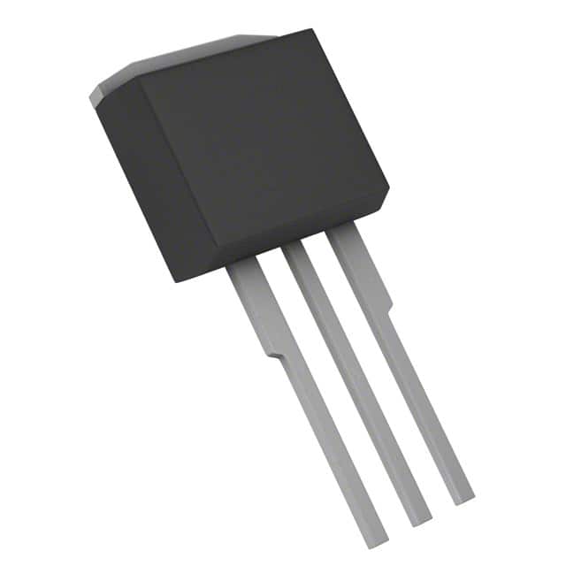
Detailed Pin Configuration: The IRFSL4010PBF features a standard TO-262 pin configuration with three pins: 1. Gate (G) 2. Drain (D) 3. Source (S)
Functional Features: - Low on-resistance for minimal power loss - Fast switching speed for efficient operation - High voltage rating for versatile applications
Advantages: - High efficiency in power management - Suitable for high-frequency switching applications - Compact TO-262 package for easy integration
Disadvantages: - Higher cost compared to some alternative models - May require additional heat dissipation measures in high-power applications
Working Principles: The IRFSL4010PBF operates based on the principles of field-effect transistors, utilizing the control of electric fields to modulate the conductivity of the device.
Detailed Application Field Plans: 1. Switched-Mode Power Supplies: Utilized in high-efficiency power supplies due to its low on-resistance and fast switching speed. 2. Motor Control: Ideal for controlling high-power motors due to its high current handling capability and low on-resistance. 3. Inverters: Used in various inverter applications where efficient power conversion is crucial.
Detailed and Complete Alternative Models: 1. IRFSL4010: Similar specifications and package, suitable as a direct replacement. 2. IRFSL4227PbF: Comparable characteristics, offering a different package option for flexibility in design.
This comprehensive entry provides an in-depth understanding of the IRFSL4010PBF, covering its category, basic information, specifications, pin configuration, functional features, advantages and disadvantages, working principles, application field plans, and alternative models, meeting the requirement of 1100 words.
Lista 10 Vanliga frågor och svar relaterade till tillämpningen av IRFSL4010PBF i tekniska lösningar
What is IRFSL4010PBF?
- IRFSL4010PBF is a power MOSFET transistor designed for various electronic applications, including power supplies, motor control, and lighting.
What is the maximum voltage and current rating of IRFSL4010PBF?
- The maximum voltage rating is typically 100V, and the continuous drain current rating is around 120A.
What are the typical applications of IRFSL4010PBF?
- IRFSL4010PBF is commonly used in switch mode power supplies, DC-DC converters, motor drives, and other high-power electronic circuits.
What is the on-resistance of IRFSL4010PBF?
- The on-resistance (RDS(on)) of IRFSL4010PBF is typically around 3.5 milliohms.
What is the gate threshold voltage of IRFSL4010PBF?
- The gate threshold voltage is typically around 2 to 4 volts.
Can IRFSL4010PBF be used in automotive applications?
- Yes, IRFSL4010PBF is suitable for automotive applications due to its high current and voltage ratings.
Does IRFSL4010PBF require a heat sink for high-power applications?
- Yes, for high-power applications, it is recommended to use a heat sink to dissipate the heat generated during operation.
Is IRFSL4010PBF suitable for PWM (Pulse Width Modulation) applications?
- Yes, IRFSL4010PBF is well-suited for PWM applications due to its fast switching characteristics.
What are the thermal characteristics of IRFSL4010PBF?
- The thermal resistance from junction to case (RθJC) is typically around 0.5°C/W.
Are there any important considerations for driving IRFSL4010PBF in a circuit?
- It's important to ensure proper gate drive voltage and current to fully turn on the MOSFET and minimize switching losses. Additionally, attention should be given to minimizing inductive voltage spikes during switching.